)
)
)
Photos © Gustav Beuermann
Photos © Gustav Beuermann
)
Fountain in front of the Max Planck Institute for Solar System Research in Göttingen. On a metallic hemisphere overflowing with water, a ring-shaped path of light can be seen in the sunshine. A close-up shows that the surface has been polished or brushed in such a way that closely spaced, fine grooves have been created in the direction of the steepest gradient. (Other scratches are not so dense and cannot be seen from a greater distance). The water layer with small capillary waves allows additional small reflections and otherwise distorts the ring only very slightly.
The pictures can be enlarged by clicking on them.
Each scratch reflects the light like a shiny wafer-thin wire: the reflected rays form a cone with the axis in the direction of the wire. In the simulation, shiny meridians emanating from the pole are considered. Depending on the incidence of light and the orientation of the pole, different gloss curves are obtained; now also in the areas that would be obscured or shadowed by a compact sphere. The latter have been suppressed here.
)
Sight-proof glass is produced by embossing a structure on one side of the hot, still viscous glass mass. If this has a certain regularity, interesting optical phenomena can occasionally be observed. This here is a pane with a fine, honeycomb-like embossing. A small light source at a greater distance, viewed through this panel, shows a pattern whose angular extent changes only slightly as you move closer to or further away from the pane, and that – surprisingly? – doesn't show six-fold symmetry.
)
)
The dark adhesive strip measures 20×4.5 mm and serves as a scale and at the same time as a focussing aid.
The exact shape of the individual structural elements cannot be seen in the photos, because you can see only distorted images of the surroundings in front of and behind the pane due to reflection and refraction and not the glass surface itself. If you look at the individual elements along a diagonal row, starting at the bottom right of the picture, you will not initially see an image of the small lamp, which is located about four metres behind the pane. Then a blue spot of light appears, in the next field it is white, and as you progress further it splits into two, and then further spots of light are added. But even from this it is not easy to recognise the exact structure.
)
Gustav Beuermann, who took the pictures, writes: “If equidistant helical grooves are milled into a cylinder (right and left, 60° pitch angle), you get a profile roller with diamond-shaped stamps. If hot window glass is suitably rolled with this, sight-proof glass with a flat side and a textured side is produced. The surface tension of the still soft glass smoothes and rounds edges and bulges.” Although the hollows and the ridges are arranged in a strict honeycomb shape, the symmetry is no longer six-fold.
And he also gives an interpretation that I am not reproducing here verbatim. The edge of the oval is formed by the rays that pass the steepest point in the respective direction of the hollow. (The hollow is narrower and steeper in the transverse direction) The “diamonds” is formed by the refraction of the rays that pass through the bulges that have swollen up between the hollows during embossing; here too, the bright edge is formed by the steepest point in each case.
So much for ray optics. But here the wave nature of the light manifests itself. This becomes particularly clear when the focus is not on the glass pane but on the sharpest image of the phenomenon.
)
)

On the left an image from a greater distance, on the right one from very close up, in which only a few structural elements are still involved.
Let us first look at the image on the left. Where you would expect to see one or two neighbouring dots of light per cell, you instead see a honeycomb pattern and individual blue squiggles at the edge. The camera has not focussed on the individual spots of light (images of the lamp). It is known that a dark centre of the light spot can then also appear on the camera's sensor [1]. The fact that the edge of the figure is blue is a result of dispersion: the refractive index of short-wave blue light is slightly greater than that of green and red, and therefore the figure is slightly larger in blue light than in green and red. Other effects also occur, but these can be seen even more clearly in the image on the right.
Right picture: If you get very close, flatten your nose against the pane and only look with one eye, you might see something like this. In the oval outside the diamond, circles of light overlap in such a way that a pattern of darker spots is created. As the radius of the individual circles is slightly smaller than the distance between the cells, the darker area is only illuminated by the cell at this point and the lighter area is also illuminated by the neighbouring cells. The size of the individual light discs depends on the defocus and the aperture of the camera or pupil [2, 3].
Interference effects are clearly visible at the edge of the figure. For example, if you first look to the bottom right, you will see darkness, as in the adjacent image. If you look a little further towards the centre, you reach the viewing angle at which a blue dot appears on the cells at a large distance. A little further on, at this angle of view, the dot becomes lighter, white, and then divides into two small spots that move away from each other. However, when these small spots of light appear as large circles on the sensor of the camera or the retina of the eye, the waves coming from the two spots overlap, intensify or cancel each other out, depending on the path difference and wavelength, resulting in the coloured stripes.
This is repeated in a similar way when additional light spots appear on the walls between the hollows, which happens at the edges of the chequer. However, the fact that hardly any colours can be seen here is probably a result of the JPEG compression of the image file. And near the top and bottom of the quad, the overlapping of light waves from neighbouring cells also leads to visible interference fringes. Of course, waves that have travelled different paths overlap at all points inside the figure. But if the path difference is large, this is no longer noticeable. Amplification and attenuation or cancellation as a function of wavelength then follow each other so closely that they can no longer be resolved.
The horizontal light stripe in the centre is a light path, which shows that areas have been created that are not curved in the vertical direction. This is to be expected on the ramparts between horizontally neighbouring hollows.
Sometimes surprising colours can be seen on spider webs under certain conditions. Mostly when the web is illuminated from behind by the sun. In photos, especially when the threads are somewhat blurred.
The spider silk and the sticky droplets on the capture threads are colourless and transparent; if colours are seen they depend on the viewing angle. How they come about has already been described here several times [1, 2, 3], but there may be new aspects that surprise. Here are observations at night in the light of a bright flashlight.
)
)
)
)
Two photos (© Michael Grieneisen) and magnified details. Click on the pictures to enlarge!
)
The radial spokes of the orb web do not have any adhesive droplets; their shiny areas are located on a circle. This circle is clearly visible in the two images above, from which one can estimate the position of the lamp relative to the web and camera. Outside the shiny parts, the radial threads are almost invisible. The capture threads with tacky droplets, on the other hand, can be seen wherever light falls on them. The sketch on the right shows an idealised web without glue droplets; the shiny parts are drawn in white. From this it can be concluded that even in the photos above the capture threads themselves are not shiny in most sectors and only the shine of the droplets sitting on them is seen. And the places where strong, highly saturated colours appear are exactly where you would expect to see the shine of the capture threads.
The following image shows the colours that appear when two coherent white beams are superimposed, between which there is a difference in their optical path length travelled, indicated in nm (nanometres) on the scale below.
)
The intense colours should therefore result from the interference of the light scattered by the droplets and the light scattered by the pieces of thread in between. The colours indicate path differences of approx. 500 to 1000 nm, but there are no well-defined light paths for the waves in the case of scattering from droplets and filaments that could be used to read off this difference. You would have to solve the wave equation for this case. That is beyond my reach.
The lower brightness of the sectors “at 6 o'clock” is striking. It must be related to the fact that the droplets are not exactly spherical, but are somewhat elongated in the direction of the thread. Thus the scattering depends on the orientation of the droplets.
Quetelet rings are rarely seen. One encounters them accidentally, but it is possible to generate them artificially and to make interesting observations.
The images below were obtained by the following means:
Mirror, width 0.43 m, fixed on the wall
Powder (Penaten)
LED-pocket lamp with a small diaphragm with 2 or 3 mm opening, fixed, distance to the mirror 3.5 m.
Smartphone, hand-held.
A dark-coloured adhesive strip prevents glare from the mirrored lamp.
)
)
)
)
)
)
)
)
)
)
)
)
Photos: © Gustav Beuermann
For this series of images, the camera (a smartphone) was moved gradually to the left at a greater distance from the mirror than the light source. This causes new colours to swell in the centre of the rings.
)
What surprised me at first was that the rings in the last pictures no longer have the colours that are so beautiful in the first few pictures. An enlarged detail from the last picture clearly shows this.
This cannot have been the case in reality. The sequence of interference colours, starting from the ring that contains the mirror image of the lamp, is always the same, but at smaller and smaller intervals.
Smartphones deliver amazingly good images, and this is partly because these devices use their enormous computing power to correct common image errors. The correction program eliminates colour fringing, and the colours that appear here were mistaken for errors and calculated away.
But it is possible that the rings or stripes were seen exactly as in the pictures. Our eye, or more precisely our sense of sight, also makes such corrections. To demonstrate this, I created the following test image. Vertical stripes with coloured edges, as they would appear when looking through a thin prism, and plain black and white stripes in the right half. If you look at the image from a distance, the two halves look the same!
)
This could be due to the fact that the colour information is transmitted to the brain at a lower resolution than the brightness information. In the next picture, on the left the red, green and blue partial images, which create white stripes on a black background on the screen, are shifted against each other to such an extent that purple (magenta) and green stripes alternate. From a greater distance, the colour impression disappears while the stripes are still visible.
)
The sun shines on a bathroom window. Bright, faintly coloured patches can be seen on it, reminiscent of oil on a wet road. They change as the observer moves. Quickly some photos. After about half an hour, I look again – the stains are no longer visible.
)
)
The outside of the glass is flat, reflecting the branches and twigs of a tree. The inner side is structured: when zoomed in closer, a square pattern of bulging surfaces can be seen. The individual reflections on it can be seen separately, interference phenomena due to the superposition of rays from neighbouring elements are therefore excluded.
A bundle of parallel light rays is split wide open by reflection from the vaulted back of the glass, as shown in the sketch below left. The corresponding reflections that could be seen from a distance are therefore faint and hardly noticeable; the reflection of the sky on the flat front is brighter.
The sketch below right illustrates that rays which are reflected back from the front side of the glass after reflection at the back side (in particular also as a result of total reflection) can be more bundled again when reflected once more and a bright boundary of the bundle (a caustic) can result.
)
)
The two sketches are schematically simplified; the bulges are likely to be approximately pillow-shaped and the individual elements are also slightly different from each other, resulting in an irregular picture. But one thing is clear: the colours are a result of the refraction of light, as in the case of the prism or the rainbow. The rays hit the glass obliquely and leave it at a different angle. Short-wave light (blue) is refracted somewhat more strongly than longer-wave light (green, red).
One evening at the end of August I found two moths in our house. Cydalima perspectalis, the moth feared by boxwood enthusiasts. (The box tree moth has invaded Europe around 2006 and has since spread widely).
I had never seen the dark variety before, so I quickly took a few photos. With flash, because it was already quite dark.
The interstice between the tiles can serve as a measure: it is 10 mm wide.
)
)
You can find SEM-images of the wing scales of the box tree moth in the Lepiforum. On the upper side there are longitudinal ribs at nearly the same distances as e.g. in the Purple Emperor or the Peacock Butterfly but their cross-section does not show any special structure. Every third, fourth or fifth one is reinforced, often two next to each other. Between the longitudinal ribs, the membrane bears fine, curved transverse ribs or folds and is perforated in the middle in fairly regular intervals.
Unfortunately, it didn't occur to me that the moths might fluoresce. It was only when they were long gone that I found this suggestion expressed in the Lepiforum, and when searching the internet, on Dieter Weiß' pages I even found a photo, quite far down in the "Fluoreszenz" section. However, fluorescence should not play a role here.
The orb web of a small spider, stretched almost horizontally between perennials, is moved by the light, swirling wind and shines and glitters in the sun against a dark background. (Sun elevation at this time about 19°.) The diameter of the spiral is about 10 cm. I also saw the spider, but could not photograph it. It was tiny, body length hardly more than 1 mm. Probably a young cross spider (Araneus diadematus).
I have described colours on spider webs before [1], [2], but the observation was made in backlight, i.e. at a small angular distance from the sun. The scattering angles were therefore only a few degrees. This time, however, the angle between incident and scattered rays was about 40° to 50°; the impression was therefore more that the light was reflected on the threads of the spider web.
)
The overexposed leaf in the background is somewhat disturbing. However, changing the angle of view changes the appearance of the net.
)
The shiny spots on the tightly stretched radial threads are clearly distinguishable from the numerous small reflections on the wind-moved and curved sticky strands.
It is noticeable that the threads shine with different brightness and also show different colours. This can be seen even more clearly in a camera-shake photograph:
)
The thin capturing lines carry adhesive droplets at regular intervals. But these are so small and so close together that they cannot be seen separately. So the threads and the droplets shine, and the light waves from these two have taken slightly different paths when they reach the eye. So it's a bit like soap bubbles where the waves reflected from the top and bottom of the lamella interfere to create coloured reflections.
)
On the left and right side of the net, the threads shine much less brightly and also in a different colour than in the front (in the picture below) and in the back. My explanation for this is that the thread lying between the droplets is partly shaded and partly hidden by the adhesive droplets and thus does not contribute to the reflection. I suspect the change in the colour of the reflections is also due to the fact that the thickness of the adhesive layer covering the threads varies between the droplets, e.g. is greater in the middle, so that the difference in path of the rays reflected at the thread and droplets is not constant.
The adjacent image shows a section of the left side of the second image. On the wind-curved trapping threads, in addition to the shiny spot, you can also see the first-order diffraction patterns, which show spectra from blue to red in some places above the centre of the image. Below the centre, only the blue parts of the diffraction image remain. (Click to enlarge!) Depending on the orientation and curvature of the filaments, the diffraction patterns – as well as the reflections – at the individual filaments are larger or smaller or not visible at all.
The blue or green sheen of the threads without bright reflections can thus be understood as part of the first-order diffraction pattern on the periodic structures.
)
)
Click on the pictures to enlarge!
The ice on a quarry pond is already thawing. The bright blue sky is reflected in it and you can see the sandy ground through the ice on the shallow water.
)
)
During melting (or evaporation?), grooves have formed between the individual single crystals, making the crystal boundaries clearly visible. Surprisingly, depending on the angle of view, individual ones of these grooves glisten in the sunlight. Not the entire width of the groove, but only one of the two flanks surrounding an otherwise non-glittering single crystal. Microscopic facets have apparently formed in the grooves, whose orientation is determined by the crystal lattice and is therefore the same for the entire seam.
In May 2018, I described this observation by Mika-Pekka Markkanen and brought an attempt to explain it, but under great doubt.
Here again the photos.
)
)
A frozen bog pond somewhere in northern Norway showing a glitter path decorated with colourful interference fringes.
Click for enlarged details!
)
) Photos © Mika-Pekka Markkanen
Photos © Mika-Pekka Markkanen
This is what Mika-Pekka Markkanen wrote when he asked if I knew this phenomenon. But I never have seen anything like that, and I don't think that many people have.
I commented on the attempted explanation at the time as follows: “The parameters used do not reflect the hexagonal symmetry of snow crystals, this is a serious flaw. But anyhow, this simulation cannot be the final answer to the problem, … ”
Some time later I got an interesting message:
“Not a scientist here, but I have observed the rainbow effect on ice in the arctic on many occasions. (I have worked in the Alaskan arctic for many years)
I always associated it with the the presence of diesel generators and assumed that it was the result of a fine layer of oil deposited on the surface downwind from the exhaust of the large generator units or in some instances diesel haul trucks. I noted that I was unlikely to see it when many miles from the vicinity of such pollution...”
Perhaps it is not the oil, but the fine particles of ice formed from the exhaust?
Just an observer.
Ray D. Congdon - KL7UT
Retired Telecommunications Technician”
I had not thought of such a possibility.
Particles, e.g. soot particles, which lie on the ice, could cause colours, Quetelet-rings or stripes. However, this does not explain the simple geometric pattern. This also applies to tiny ice particles. Slightly larger ice particles – snow crystals – could produce spectral colours, but these are different from the typical interference colours and would have to form rings around the sun's reflection. Therefore, a very thin oil film seems more likely to me. However, you can't see any colours on the ice surface in the foreground. A coherent oil film should look on the ice like on a wet road, this case can be excluded. But one can imagine that small oil droplets, when blown over the ice by the wind, preferentially stick to the minute steeper spots.
The first image in the row below shows where the sun is reflected when the surface elements are not tilted (only one point), tilted by 3.5° (along the smaller contour) or tilted by 8°. (The sun elevation here is 10°, this is also approximately the case in the photos). Comparing this with the photos, we see that most facets contributing to the glitter path are inclined by less than 3.5°, but a smaller portion have inclinations up to about 8°. Randomly oriented surface elements inclined by up to 8° can, however, only cause reflections within the 8° contour, even if a second reflection is taken into account, and in this case no light comes to the eye from the area where the colours are seen. So there must be surface elements that are so steep that they do not contribute to the glitter path, but which reflect the light that has already been reflected once into a larger solid angle. The second image below shows where twice-reflected light is seen when randomly oriented facets with 3.5° and with 60° slopes are present (grey area). Note that the highest point of this area is lower than the horizon. This is already consistent with the photos. But colour is not yet produced in this way.
Colour is obtained when there is a thin film of oil on the steeper facets. Under the influence of the adhesion force between oil and ice, surface tension and gravity, the oil could then collect at the edge of the tiny bumps or steps as sketched in the third image in the series below. The colour produced by the interference of the light reflected at the upperside of the oil film with that reflected at the interface between the oil and the ice depends on the thickness of the film and the angle of reflection, and if we assume that the film thickness decreases with the steepness of the surface, we can eventually, with a few plausible assumptions about the geometry, obtain an image like the last in the series.
)
)
)
)
The probability of a light ray hitting a steeper slope after the first reflection is greater the flatter the ray. Without attempting to model the ice surface, one can take this into account by choosing a suitable probability distribution for the orientation of the surface elements for the first reflection, in the simplest case that one assumes a uniform distribution in a given solid angle, as done here.
The dependence of the reflection coefficient on polarisation and angle of incidence was not taken into account; only a rough estimate was attempted in order to find the cause of this phenomenon. A correct calculation with the help of Fresnel's formulae would change the relative brightnesses of the individual colour bands, very probably greatly attenuating the outermost white band.
Pollution by diesel exhaust. A bit disappointing.
While gardening, one sometimes brings an earthworm to light. And when the sun is shining, you can also see the worm shimmering. I remember observing this many years ago, when I didn't have the opportunity to document it with photos. Meat also sometimes shimmers greenish or reddish; it can probably be explained in a similar way, I thought, and was not very surprised about it. Later I read that the shimmering was caused by the bristles of the worm; I don't remember where I read that.
Since I rarely dig in the garden lately, I have not yet been able to photograph this apparition. But recently Aleksandr Berdnikov sent me some pictures. About the shimmering he writes "I've seen it attributed to tiny bristles", but seemingly he is not convinced.
)
)
This looks very puzzling. But the following picture, where the worm curls around a finger, gives a clue to the correct explanation:
)
)
It reminds me of the diffraction on a CD. The coloured reflections occur where a glitter path would run if the structure were coarser. So I try to find a structure that provides the appropriate glitter paths. The shape of the worm winding around the finger is approximated by a torus. On this torus there are supposed to be glossy lines. They reflect the light to the eye where the light ray from the sun makes the same angle with the line as the light ray from the line to the eye, or more precisely: when the two angles differ only slightly. Adjusting the parameters, I got the picture to the right above. The two glitter paths intersect at the point where one would see the sun's reflection on the torus surface.
“Externally, the entire body of the worm and thus also each of its segments is delimited by a skin muscle tube. A single-layered epidermis, which contains some glandular and sensory cells and is surrounded on the outside by a collagen-containing cuticle, is followed by a ring muscle layer. This in turn is followed on the inside by the thick longitudinal muscle layer.” (Translated from the German Wikipedia).
“The epidermal cells are arranged in a single-layered epithelium in which glandular and sensory cells are interspersed. They secrete a delicate (in earthworms approx. 1 µm thick), often iridescent cuticle. Inside the epidermis is the muscular tube consisting of obliquely striated muscle cells, which is composed of an outer ring and an inner, much more powerful longitudinal muscle layer.” (Translated from this source).
)
It is an obvious conclusion that the collagen strands in the cuticle are arranged as in the sketch above, forming a very fine mesh. This net allows the worm to stretch or shorten without the lengths of the strands changing. Since the collagen has a different refractive index than the moist matter between the strands, perhaps also because the strands create a slightly wavy surface structure, this acts like a diffraction grating of lines crossing at approximately right angles wrapped around the worm. (That periodic changes in refractive index can produce coloured reflections has been shown earlier).
From the position of the reflections, the size of the grating constant or the distance between neighbouring strands can also be obtained: the first-order diffraction reflex occurs when the path difference of the reflections on neighbouring lines is equal to the wavelength λ. But calculating this is not so easy, so I content myself with a rough estimate. I consider a certain wavelength, λ = 500 nm (bluish green) and let the corresponding reflection occur at the point marked by a green blob in the neighbouring sketch. The estimation gives a little less than 500 nm for the distance of the lines at this point.
)
The photo on the right shows the diffraction of light at an approximately square, much coarser cross-grid (a curtain). Can we expect other reflexes on the worm? The ones described so far correspond to the first-order diffraction patterns on the left, right, above and below the direct reflex. The more distant second order will not be visible because of the fineness of the grid. But the reflections lying in the diagonals?
To verify the explanation, Aleksandr took a few more shots. To see the iridescence, he had to put a worm in the right position.
Note in the left picture the reflection on the left side of the top of the worm, in the right picture the reflection on the right side near the bottom of the picture. So everything fits together.
)
)
However, other colour appearances are possible, as the following picture shows. Here it is not diffraction that is the cause, but, similar to an oil film on wet pavement, the thin cuticle, whose refractive index is somewhat different from that of the epidermis underneath.
)
Incidentally, the last photos show that the worms under consideration are not the common earthworm Lumbricus terrestris, as initially suspected, because they show a feature that the latter does not have, numerous regularly arranged tiny bristles along a ring around the middle of each segment. They could be a species from the genera Amynthas or Metaphire, originally Asian earthworms but invasive in North America (where the photos are from). If they iridesce, however, this is likely to occur in the same way in all oligochetes. So far, I have only been able to observe it in Lumbricus terrestris.
After the first observation of dew diffraction on a window pane, I did not see this again. But if you breathe on a window pane, you can get quite similar diffraction aureoles. As I wrote, this doesn't work as well in summer when it's warm as it does in winter, so I took a few more photos of dew aureoles last winter.
This went like that: the camera was placed on the window sill with a small tripod and manually focused on the distant street lamp. A roll of paper was then used to breathe on the window in front of the camera and then a photo was taken with a two-second delay (to avoid blurring). Then breathing again … and this procedure was repeated a few more times. The result can be seen below, and below that, for comparison, the results of an attempt to simulate this computationally.
)
)
)
)
)
)
)
)
)
)
)
)
)
If a pane of glass is only very delicately breathed on, the distribution of the small droplets can be expected to be reasonably uniform, because where one droplet has just condensed, the vapour density is lower and heat of condensation has been released, so that the probability of a second droplet condensing very close by is small. One can assume a certain minimum distance between the droplets.
With further breathing on, the droplets enlarge and when two of them touch, they flow together. Probably they do not then contract to an exactly circular area. Thus, with more dew, there is certainly a mixture of droplets of different sizes whose orientation, if elongated, is random. All of this is difficult to take into account, so only a highly simplified model is examined here: droplets with a circular outline, whose size increases with the strength of the dew, which are statistically distributed and do not touch each other.
In a first attempt to understand the strange aureoles, I treated the dew droplets as opaque, i.e. black, circular discs. If one changes the size of the discs in this model, the angular extent of the aureole changes, but the colours and their order do not change. This approximation, as it now turns out, is only good for very small droplets; for larger ones, one must not neglect their transparency. To keep the calculation simple, tiny fictitious, infinitely thin lenses are considered instead of the droplets, whose influence is taken into account by a position-dependent phase shift of the incident plane waves in the area of the lens.
Fraunhofer diffraction was calculated on a small, dewed circular disc, the diameter of which was chosen so that there was room for approx. 500 droplets each. Their distribution was determined by a random generator, with the constraint of a given minimum distance. A pointlike light source infinitely far has been assumed, with coloutr temperature T = 5604 K. By varying the parameters (radius, height, minimum distance), an attempt was made to imitate the images in the top row.
There are undoubtedly certain similarities between the two series, but there are also clear differences. Some of these can be easily explained:
The distinct radial stripes are due to the fact that the number of droplets used for the calculation is much smaller than those included in the photos. With the focal length set at 17.5 mm and aperture f/5, the diameter of the aperture is 3.5 mm. Since the camera was close to the window pane and the light source was far away, the area captured is given by the size of the aperture. The maximum diameter of the circular area used in the simulations is 0.9 mm (last picture, there the droplet radius is 13 μm. In addition, the lamp is not a point light source, which also leads to a blurring of any details.
The fact that the spectrum of the street lamp differs greatly from that of a black body, which was assumed in the calculations, should be irrelevant.
In the first picture in the lower row, the correspondence with the photo above is very good. The droplets here are very small (diameter approx. 4 μm, i.e. four thousandths of a millimetre), their (fictitious) height is 0.6 μm and a minimum distance of 6 μm (centre to centre) was assumed. These small lenses have a very short focal length, so they disperse the light very strongly and this results in very little light coming from there to the observer. (Therefore, in this case, the approximation of calculating with black discs already leads to good results).
The second image in the top row shows most clearly that the window pane was unevenly aspirated, so separate adjustments were attempted for the left and right halves, which can be seen in the half-images below.
It turns out that the simulation delivers more colourful and contrasty images than reality due to the idealising simplifications, the colours change in radial direction in finer gradations.
In summary, the surprising changing colours of the aureole are due to interference of the light passing through the droplets with the light passing between them, and the dark area around the bright centre is a consequence of the short-range correlations between the droplets, as already explained on the occasion of the first observation of the dew aureole.
It was not until 2008 that it was discovered that ripe bananas fluoresce blue (Bernhard Kräutler et al.: Die blaue Lumineszenz reifender Bananen - Angewandte Chemie Vol. 120, No. 46 (2008) p. 9087). Cause is a degradation product of chlorophyll that decomposes slowly. See also Chemistry in Pictures: Blue bananas.
)
)
This fluorescence is particularly strong in the vicinity of the brown spots that form when the cells in the peel decay.
)
)
I think it's strange that the knowledge that they are yellow lets you think when you look at the blue fluorescent bananas that you see a somewhat yellowish blue, which, of course, can't exist. But this is at least my imperession. This is perhaps also due to the contrast with the brighter fluorescent parts of the scene.
If the bananas ripen further, the bright fluorescent rings fade away and the overall glow diminishes and finally disappears completely. Surprisingly, however, the pale inner side of the peel continues to fluoresce even when the peel has already dried out.
)
)
In varying autumn weather with occasional rain showers, there were often beautiful rainbows in strong colours.
)
You almost think you can see all the spectral colours – red, orange, yellow, green, blue and violet, although blue and violet are already very “diluted”. In order to be able to judge this better, the photo is covered with a grey mask that leaves only some areas free. First, however, the positions of the exposed areas:
)
)
Even the strong red at the outer edge of the bow no longer appears so strong here in a neutral environment. And if a black environment is chosen instead of grey, you can see even better how low the colour saturation is in all cases:
)
Against a light grey or white background, one sees the colours differently again, the red is now brown, the yellow olive green, the violet can hardly be guessed anymore:
)
Here it becomes clear how variable colour sensations are and how strongly they are influenced by contrasts.
A box made of synthetic resin reflects the light from the overcast sky, and very faint colours can be seen because of the internal stresses and the resulting birefringence.
)
In oblique incidence, the light reflected from a smooth surface of a transparent body is partially polarised. If the reflected and the refracted ray are perpendicular to each other, even one hundred percent; the corresponding angle of incidence is called Brewster angle. Then only the light is reflected whose electric field oscillates perpendicularly to the plane of incidence (s-polarisation; the plane of incidence is spanned by the surface normal and the beam direction), while the light oscillating in the plane of incidence (p-polarisation) passes the interface unattenuated.
The light reflected at the top of the acrylic glass is polarised, but you won't notice it if you don't use a filter. The light reflected at the bottom side, also polarised, now passes through the material which is birefringent due to the inner tensions and is split into an ordinary and an extraordinary beam, between which a phase difference results, as described in more detail elsewhere.
The following pictures were taken through a polarisation filter.
)
)
In the left picture, the direction of the filter in front of the lens is such that the s-waves are blocked; this situation therefore corresponds to a birefringent medium between crossed polarisers. Without birefringence, the whole surface would be almost black.
In the right picture the filter position is rotated by 90° compared to the left picture, the s-waves are let through and the p-waves are blocked. Without birefringence the surface would be uniformly white.
The fact that colours can already be seen, even if only weakly, without a downstream polarisation filter is due to the fact that when light reflected from below passes through the upper interface, the p-waves are hardly attenuated, while a significant portion of the s-waves is reflected again and is therefore missing in the transmitted light.
In a birefringent medium, linearly polarised light generally becomes elliptically polarised. This can be seen as a superposition of two perpendicularly linearly polarised wave trains or as a superposition of right and left circularly polarised waves of different amplitudes. With circular polarisation filters, as used in glasses for 3d films, these can be shown separately:
)
)
The additive superimposition of the two images should actually look like the first image at the top of this section. This means that the colours seen in the left and right images at corresponding positions are approximately complementary. Approximately, because the uppermost picture shows weak colours, but in addition, the pictures were taken freehand and the viewing angle is therefore not exactly the same on the left and right. (In addition, analysing the circular polarisation by a filter works exactly for a single wavelength only, but the effect of this shall not be investigated here).
You can easily test a special feature of our visual sense with the smoothly merging colours. In the next picture a fixation point in the middle was marked with a +. If you stare at this point for a longer time, the colours fade and disappear completely after about 30 seconds. This happens faster if you look with one eye only. The fact that parts disappear from the field of view when the eyes do not move was first described by the Swiss physician I.P.V. Troxler, hence the name. It is caused by the same “mechanisms” that produce afterimages. Continuous transitions between the different areas reduce the effect of unintentional eye movements that otherwise delay or prevent the effect.
)
If you then look at a white area (click on the image!), you will see the negative as an afterimage for a short time. It is also interesting how the afterimage changes: first, the colours appear and disappear, the difference in brightness decays much slower.
Aleksandr Berdnikov took this image of a Fresnel diffraction pattern on a fly's eye. I have shown such patterns on dragonflies' eyes earlier, but this image is different in that it clearly resolves the single facets of the compound eyes.
)
Aleksandr writes:
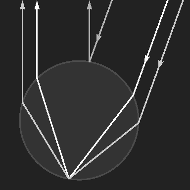
“My explanation of it is that (simplifying) each individual facet of the eye is a spherical mirror that produces a point light source – the image of the sun – somewhat below the cap. So the reflected sunlight is basically as if originating at that point and passing through the hexagonal aperture of the facet cap: it spreads in a hexagonal cone and has edge diffraction pattern near, well, the edges.
And we see this intensity distribution «mapped over» the eye, as the direction of the reflection cone follows the orientation of the facet, so for a (not that) faraway camera, each facet allows to probe a corresponding point of the cone.”
The angle of aperture of the reflected light cones is much larger than in the dragonfly eyes shown earlier, the diffraction maxima and minima are only visible at the edges and correspond to those which would have to appear at edges of all shadows if the light source were punctiform. However, the angular extension of the sun disc is so large that these phenomena are averaged out in the penumbra.
Today, when digital photography is mainly used, the negative has lost its importance. However, common image processing programs offer the possibility to convert an image into its negative. The result usually looks quite plausible. Here is an example:
)
)
The reason for investigating this was the demonstration of experiments with a prism. If one looks at a white stripe on a black background and a black stripe on a white background, the two images should behave to each other like positive and negative or, in other words, the complementary colours should be visible at corresponding positions.
The first picture in the row below shows the template, the second one shows it photographed through a prism. It should be noted that the colours seen when looking at the narrow white stripe through the prism are all outside the gamut displayable on the screen. In contrast, all colours in which the black stripe is seen on a white background are exactly reproducible. The second image can therefore only roughly reproduce what can be seen in the right half. The fourth image was created by converting the second one with an image processing program into a “negative” – it should actually look like a mirror image of the second one.
)
)
)
)
In the images, the brightnesses of R, G and B are coded for display on the screen by numbers L ranging from 0 to 255. If one replaces L each by 255 − L, one gets the inverted colours in the fourth image. This way, the reversal is done by the image editing programs.
In order to obtain a correct negative, not the perceived brightness must be inverted, but the physical intensities Y, which are non-linearly related to the brightness via the so-called gamma correction. This calculation was done to get the third image in the row above. Well, it doesn't look exactly like the mirror image of the second one either, but it is more similar to it. The reason for the discrepancy is that the exact colours cannot be displayed, and for those projected into the displayable area it no longer holds that the left half of the image is the negative of the right half and shows the exact complementary colours.
Below to the right now the correct negative to the example above:
)
If you are interested in details, continue here!
The illuminated side of the moon points to the sun – but why does it look like it's pointing a little further up when the sun is low or has already set?
For a panoramic picture the explanation is quite simple. The three-dimensional image is projected onto a cylinder jacket and this is then spread out. Straight lines are thereby generally projected onto curved lines.
)
A panorama stitched from two images using AutoStitch. Near the upper left corner the moon can be seen, on the right between the roofs of the houses the sun.
Since the moon is so tiny in the picture, on the left a detail of the photo in original size, where you can see the direction better.
When moon and sun are both in the sky, what you perceive surprisingly(?) corresponds to the panoramic image, the moon seems to be illuminated not by the sun, but from somewhere higher up. Minnaert (1937)[1] writes about this [2]
The explanation is basically quite simple. When we look at the moon, we can easily imagine a straight line running in the direction of the rays incident on the moon. If we then turn our head and look in the direction of the sun, we will not be able to find this imaginary line again and continue it correctly to its vanishing point in the sun as long as we do not have any additional aids like the taut string mentioned.
When we see the thread while we turn the head, its image on the retina changes. This change is hardly noticeable, because we do not perceive the images on the retina, but we see what is outside; here that the string is straight and maintains its position. Spatial vision requires an immense amount of data processing, which we hardly ever become aware of. And with a straight line that is only imagined, the necessary information to take into account the imperceptible changes is missing.
However, there is another trick to circumvent this deficiency: if the rotation of the head during the change of view is about an axis perpendicular to the plane containing the sun, the moon and the eye, then the image of the imaginary line on the retina does not change and the continued straight line hits the sun [3].
[1] M.G.J. Minnaert, "De Natuurkunde van't Vrije Veld", vol. 1, 1937
[2] M. Minnaert "The nature of LIGHT & COLOR in the open air", Dover Publications Inc., New York 1954, ISBN 0800759201969; p. 152
[3] U. Backhaus und H.J. Schlichting, "Der Silberblick des Mondes" MNU Journal 4.2017
)
It is not easy to document the colour of the sky by photographs, and this is especially true at twilight. This is due to the fact that the illumination changes a lot during the course of the day and that our perception of colour adapts to this change. In order to make photos look natural, this adaptation should be taken into account; this is done by the white balance. A neutral grey surface should also appear in the photo as a neutral grey, just as we perceive it. The colour of the illumination is, so to speak, compensated by the white balance; the scenery should look like it would look like in „normal daylight“. Daylight white is the illumination D65, approximately the colour temperature of 6504 K.
But if you want to see the colour of the lighting itself, in this case the sky, in the photo, you shouldn't actually do a white balance, but would have to set D65 as white. But – does the result then correspond to the sensation?
The following pictures demonstrate this:
)
)
)
Photos taken on 18 December 2019, half an hour after sunset. The pictures can be enlarged by clicking on them!
The left and the middle picture show the same photo. On the left with white balance at 6500 K, in the middle at 10000 K. Even though the left image is the most faithful representation of the colours, the middle image is more faithful to the visual impression. Above the red near the horizon, I saw the sky more grey than blue.
With the setting to 9000 K and a slight shift on the red-green axis towards green, the colours result as in the right picture, but this one was taken with the same camera and with the same setting as the large picture above. It also comes very close to the subjective perception.
The simple camera I used for the photo of the sunset in 2006 didn't offer the possibility to save the raw format. The white balance was set to “cloudy weather” and as far as I could judge then, the colour rendering was quite good.
Something else stands out about the picture, namely JPEG compression effects.
)
The fact that we perceive differences in brightness much more clearly than differences in hue at the same brightness is exploited in the JPEG compression of an image by storing the colour information at a lower resolution than that of brightness. The measured values R, G and B for each pixel are converted into brightness and the two colour channels “Blue—Yellow” and “Red—Green” for this purpose. Details will not be discussed here.
The loss of information in photographs is rarely noticeable, but in the first picture above you can see on closer inspection that the colour of the sky does not reach the dark branches in many places. On the right you can see a part of the picture in original size, by clicking on it you can enlarge it to two to one.
For the physics behind blue sky and afterglow see the section on scattering.
During the day, on 10 November, the weather had been cloudy and damp, but in the evening it cleared up. During the night I noticed that fern frost had formed on the outside of a sloping garret window. The street lamp opposite illuminated the window and the already bare branches of the tree in front of the house cast their shadows on it.
Years ago I had seen similar frost [1], and also this time the strange, almost periodically repeating glittering along the middle lines of the individual swathes appeared.
)
)
)
The swathes do not show the same pinnate structure as the last ones, probably because the water film on the window was a bit thicker this time. Instead of pinnules one sees here a seemingly three-dimensional structure, like a tangle of roots branching down. The distance between the glittering areas was six to seven millimetres. As an explanation of the almost periondic repetitions of the structures I can offer what I have essentially already written years ago:
The growth happens by accumulation of molecules, thereby heat is released, which, if not removed, inhibits further growth. The outer corners are favoured for both deposition and heat removal. The star-shaped dendritic snowflakes are well known, but flat as well as narrow hexagonal prisms are possible too.
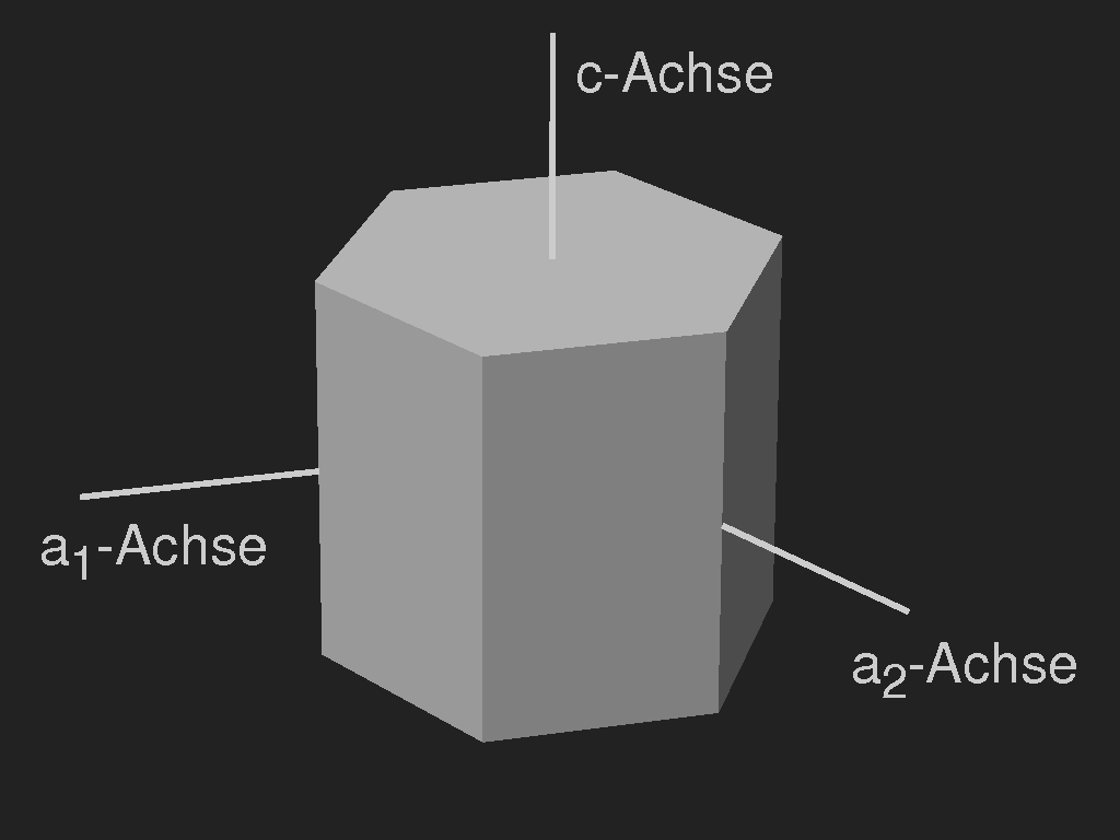
The curvature of the individual dendrites is probably caused by temperature differences which, due to the uneven expansion of the crystal lattice, favour the formation of lattice defects, causing the orientation of the crystal lattice to change slowly as growth progresses. Assume that the c-axis is parallel to the glass surface and that the dendritic growth preferably occurs in the direction of the a-axes. The crystal lattice can bend to the sides, but also up or down, while the dendrites are bound to the surface because they cannot grow out of the water film. At the top surface, they form facets whose orientation is determined by the crystal lattice and thus changes slowly. The periodicity interval corresponds to a rotation of the lattice by 60°. This is illustrated schematically in the following figure.
)
The change in the orientation of the superficial facets causes both the periodic occurrence of the bright spots along the band axes and the differences in brightness across the axes, giving the impression of spatial depth.
Autumn, the sun is already low, and along the path along the water stands reed (Phragmites australis). On the panicles with the seeds ripening in spikelets, the hairs that spread the seeds by the wind shine in the sunlight, and various optical phenomena can be observed against the light.
)
)
)
The shiny spots of the hairs give the impression of rings around the sun. This phenomenon was discussed in more detail using the example of wet twigs [1] and has already been shown several times [2], [3].
In the next picture you can see the lustre of the thin hairs in delicate colours. The colours come about when the light rays, which reach a point on the camera's sensor from neighbouring spots, differ a little in the distance travelled, superimpose each other, whereby parts of the spectrum are attenuated or extinguished by interference, others are amplified. Such interference colours in backlighting against a darker background can be seen on many thread-like structures, thistle seed hairs [2], caterpillar webs [3] and especially clearly on cobweb threads [4]. These colours are not so good to see with the naked eye, because they are clearest when the threads are a little outside the focal plane, and when you look at them you focus involuntarily.
)
Whether and how clearly effects of Fresnel diffraction become visible in the photos depends on the parameters of the camera; diffraction occurs at the aperture and is therefore not visible to the naked eye in this form either. The aperture here was f/7.1, the focal length f = 8.4 mm and the pixel pitch 1.5 m.
The diffraction effects are shown in the form that a bright point outside the focal plane is not simply blurred, but shows a pattern dependent on the shape of the aperture, as already described using the example of rainbow reflexes on dew droplets [5]. Where the hairs shine along lines, diffraction shows that instead of a diffuse line two or three lines separated by darker stripes can be seen, single gloss spots show a dark center.
)
)
The following images were taken in Wunstorf (9.27° E, 52.25° N), the solar altitude was computed from this and from the time of the image.
)
)
)
The clouds consist of tiny ice crystals up to about 100 nm diameter and form at altitudes of 76 to 85 km (English Wikipedia) or 81 to 85 km (German Wikipedia). By day, these clouds, even if they are present, cannot be seen, they are very thin and transparent and are outshined by the sky light. But when they are illuminated by the sun at night or at dusk, while the deeper air layers are in the shade, they become visible.
It is not easy to reproduce the pictures as they were originally seen. There are several reasons for this. On the one hand you don't see colours in darkness (scotopic vision), at dusk (mesopic vision) the colours are not as good as in daylight (photopic vision). And what then are the right colours that you want to document? I have already mentioned this problem in connection with the polar light. In darkness you cannot rely on the automatic white balance of the camera. This becomes particularly clear when, as here, different light sources are involved. The street and the bushes in the foreground are brightly illuminated by a street lamp, a satisfactory compromise with the night clouds in the background is not possible.
)
)
The images were saved in raw format so that the white balance could be adjusted later. I didn't see the night sky in blue but in grey and therefore set the colour temperature for “White“ to 6500 K (which corresponds to daylight in the shade).
Since the scattering ice crystals are small compared to the wavelengths of the light, the shorter wavelength light is scattered more strongly than the longer wavelength light and the clouds therefore appear bluish, as described in the chapter on scattering (Rayleigh scattering, Tyndall effect). However, the further away the clouds are, the more the hue shifts towards yellowish-reddish, again due to the scattering in the air. And also the clouds seen at the highest possible altitudes are not bluish. The rays by which they are illuminated have travelled a long way through the lower, denser layers of the atmosphere and are therefore orange to reddish like the light of the setting sun.
)
)
)
)
)
If a thin layer of ice has formed on water, you can observe the colours resulting from birefringence without any aids when the weather is fine, i.e. the sky is blue. Is it surprising that only the mirror images are coloured? Daniela took the three pictures without polarization filter. (With a filter also the ice plates themselves would appear coloured).
How does it happen? – this phenomenon has been explained in the section polarisation and birefringence using the example of a plastic box, and also when colours photographed in a greenhouse were shown.
)
The sun shines through gaps between the clouds and in the air turbid by haze or dust one sees the parallel rays perspectively like a fan. This is not a rare sight. When the sun is low the crepuscular rays can extend over a large part of the sky.
)
Sunset in the east of Greenland on 31 January 2019.
Photo: © Kamilla Oliver (shadesofsnow). Shown with permission.
Here not clouds but a mountains ridge model the crepuscular rays. The clouds above the rays visible in the haze are illuminated from below by the setting sun. On the next picture the illumination of the cloud underside is even better seen.
)
Sunset, Greenland, August 10th, 2018. © Kamilla Oliver
There are no rays visible, but shadows are cast by the lower parts of the clouds onto the higher layers. This indication for the spherical shape of the earth is rarely so clear.
)
No crepuscular ray, but a glitter path on the cloud which is illuminated from below. Platelet-shaped ice crystals in the cloud, which align themselves horizontally as they sink wobbling around this mean position, reflect the sunlight. Usually, this phenomenon is perceived as a vertical light pillar (the usual name), but it comes into being in the same way as a glitter path on water, only turned upside down.
)
With the naked eye, the wind turbines were hardly visible (Wide angle image, medium focal length); they were “zoomed in”. Assuming straight light rays and a straight background, this image would not be possible. But you can clearly see the mirages downwards, so the light rays that produce this mirror image are curved.
)
The picture was taken on March 18, 2018; the air layer directly above the water surface must have been slightly warmer than the layers above, so that the rays bend upwards. The adjacent sketch shows this schematically (and exaggeratedly). At the bottom the air is warmer, the refractive index smaller and therefore the wavelength longer than at the top.
The jagged wavy borderline between sky and water is not the horizon, but the lower edge of the mirror image. The horizon is at the height where the rotor blades and their mirror image seem to touch in the rounded bend.
A slight curvature of the light rays in the atmosphere is always present, since the density of the air and thus its refractive index depends on the altitude and the temperature. This is particularly noticeable in the case of almost horizontal lines of view. Since the density of the air generally decreases with increasing height, the rays are usually curved very weakly downwards. As a result, range of vision is larger than it would be without refraction, and this can be taken into account by using an apparent curvature slightly smaller than the curvature of the Earth's surface (larger apparent Earth radius) in the calculations. (According to Wikipedia the mean observed apparent earth radius is Rapparent ≈ 7680 km.) This will be explained in more detail below.
However, the temperature distribution plays an important role. If the temperature increases upward, the visibility can be increased strongly if the light-rays follow the earth-curvature, and there can occur even mirages upward (Fata Morgana).
)
According to a map of the offshore wind turbines in the German Bight, these wind turbines should belong to the wind farm Borkum-Riffgrund II.
The picture was taken at the end of June, when the weather was very warm. The water was colder than the air, so that the lower air layers were probably cooler than the slightly higher ones (inversion) and the normal trend in temperature was only reached at higher altitudes.
How much do light rays bend in the atmosphere? READ MORE …
)
)
)
The low autumn sun shines on the glass entrance door of the Lower Saxony State Museum in Hanover, Germany. Light hitting the bevelled edge is refracted and split into a spectrum, as schematically sketched in the middle. To the right the enlarged detail shows that at larger distance from the prism, the spectrum shows only red, green, and blue. (This has already been noticed by Goethe, see e.g. one of the plates added to his Theory of Colour, Tafel V, which, apart from the faded colours, has much in common with the present sketch.)
)
The reflection of sunlight by structures exhibiting some regularity may produce light columns or curved paths, depending on the geometrical conditions.
When looking through a crisscross of glistening silk towards the sun, the glosses seem to form circular arcs around the sun. Likewise light rings are seen when looking through the wet twigs of a bare-branched tree towards a street lamp, or when a light is reflected by a scratched glossy plane. Ireggularly oriented strands or scratches seemingly always produce circles.
If, however, the scratched glossy surface is not plane, the apparent curves are no circles anymore. I noticed this when I recently saw a spider web glistening. The sheet web – a tangle of strands within a thin nearly horizontal layer – was visible only in its glistening parts.
To figure out which patterns might occur under which conditions strains spatial imagination. To see some simple examples may help.
Instead of a spider web we consider an invisible cambered surface to which glistening needles (tangents) are attached at random points with random orientation.
The surface is given by the equation
For the sake of reproducibility, the other parameters are given: the length of the needles is 8 mm; drawn are only their glistening parts for which the difference of the angles between incoming ray and needle and needle and direction towards the eye is less than 0.25°. (The apparent diameter of the sun is 0.5°)
)
)
)
)
)
)
)
This accidental observation is completely different from all my previous ones. I was surprised (but not amused) by an otherwise interesting video on YouTube (in German). There the topic is that sometimes it is controversial whether a given bluish green (or greenish blue) is green or blue, and some weird hypotheses on colour vision. But in the introduction, the colour yellow is discussed, and a distinction is made between “real yellow” and the “illusion of yellow” produced by additive mixing of red and green on the computer screen. According to this video – and to that one too –
Apparently it is a popular fallacy that “every colour has a certain wavelength”. And the colour yellow is the best example to show that this in not true. Only a prism is needed.
Indeed, according to Helmholtz most colours can be characterized by a wavelength of the same hue (the exceptions are the purple hues between red and violet). But to see colour on a surface, it must remit a non-negligible fraction of the incoming (white) light, certainly not only “one wavelength”.
For the following pictures a nice flower had to sacrifice one of its ray florets. From that, a narrow streak was separated and photographed on black paper, in the second image below through a glass prism. (The experimental arrangement is the same as described earlier.)
By the prism, the light coming from the yellow streak is spread out to a spectrum, showing that the red and the green portion of the light is remitted, and only the blue light is absorbed. Yellow is always “white minus blue” and thus the sum of red and green. Yellow or any other colour consisting of only one wavelength (one spectral line) is only possible for light sources like lasers or other special light emitting devices.
)
)
)
)
The right pair of images shows photographs of the first picture in the row, taken from the LCD flat screen, the last one again through the prism. While the third photo is hardly distinguishable from the first one, the fourth is quite different from the second one. In contrast to daylight, the white light backlighting the screen consists of only few narrow lines or bands and a broad continuum only in the short-wavelength (blue-violet) region.
The last picture differs, however, from the visual impression when looking through the prism at the leftmost one, in that the weak blue line cannot be seen (at least, I can't see it), and the green line is stronger – the sensibility curves of the camera clearly differ from those of my eyes. Moreover, remember that it is impossible to render a spectrum faithfully on the screen or in print, see the sections on white light and the prism experiments.
The spectral composition of the yellow light from the screen is different from that remitted by the yellow flower – but this is generally the case for every colour and every possible method of colour reproduction.
Glass which is buried in the soil slowly decomposes. The alkali is leached out from the surface layer and the silica rich remnant then partially crystallizes and is likely to get fine cracks and to separate from the bulk, thus making the layers beneath accessible to weathering. The result of this decomposition is often a patina consisting of thin stacked layers which exhibits vivid iridescence.
Now I got a cullet found when gardening, probably a fragment of the rim of a thick-walled wide dish. Its size is about 70 × 50 mm, measured along the diagonals. How old it might be?
)
)
)
)
The outermost brownish layer flakes off when touched, thus exposing the layers beneath and their blurry iridescence. In transmitted light, only the green colour of the bulk is seen.
A moderate thunderstorm was over, in the west it was still raining as the sky glowed bright red. From my position the sun could not be seen, its height was only 0.16° (computed from data given in Wikipedia), part of it was already below the horizon.
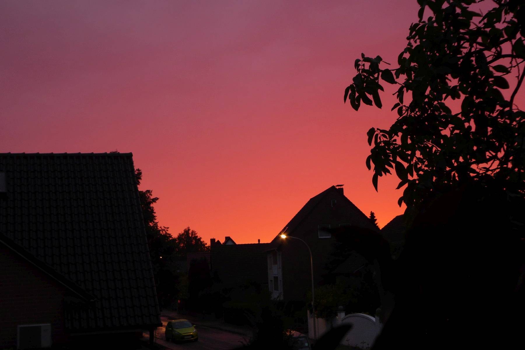
)
In connection with the classification of rainbows, this phenomenon has been called “zero order glow”. Order in this case means the number of internal reflections in the raindrop. The light seen here thus has not been reflected but only fanned out by refraction. I have already photographed this once (“Behind the rainbow”), then the sun was slightly higher (about 2°) and the glow wasn't red but orange-yellow.
To the right in the left half of the image the incoming rays from the sun and the reflected ones which form the rainbow are shown; in the right half the rays refracted by the drop acting like a thick convex lens.
Each one of the falling raindrops in the field of view contributes a tiny speck of light in the colour of the setting sun.
Recently my attention was caught by a spider's horizontally extended sheet web which showed light rings and paths of light glistening in purple and green colours. The images below show the same area viewed from slightly different directions; to the right a detail of the left image.
)
)
)
)
The web – a tangle of lines within a thin, slightly undulating sheet – extends over the whole area of the image, but only the glinting parts of the threads are visible. Light rings formed by the glints are not circular, but oval – the imagined lines resemble contour lines on a map. This is due to the camber of the sheet containing the strands and shall not be the topic now.
)
)
)
)
| (a) | (b) | (c) |
Besides white, i.e. colourless reflections there are purple ones as well as green ones. What causes these colours?
Colours seen on spider webs in most cases occur if the web is looked at against the light when there is a dark background. Light scattered by small angles conveys the colours. But here now the scattering angles are large. If the sheet web were a membrane, the sun would be reflected at the brightest spots, similar to the reflections in the image to the right which shows a membrane produced by a snail. It is suggestive to speak of reflection instead of scattering in this case.
How the reflection of the sun in a transparent cylinder looks like depends on the viewing direction. To the right there are three macro-photographs of a nylon wire of 1 mm thickness. (a): only one reflection at the front side – the angle between illumination and observation (projected onto the plane perpendicular to the line) exceede the rainbow angle –, (b): to the left of the narrow reflection at the front there is the double reflection at the back, and at the right rim there is some light which has been reflected twice. (The double reflection from the back arises because there are two different rays which are deflected by the same angle, see the sketch below and the discussion of the rainbow.) In image (c) the direction of the strand, the sun, and the observer's eye are in the same plane. The reflections from front and back side overlap in the middle, and near both rims there is light which has been reflected twice at the back.
However, the silk strands are so thin that geometrical optics is no good approximation any more. The exact solution of light scattering by a transparent cylinder is available and may be found in the standard work of van de Hulst [1]. But presumably the cross section of s silk strand is not exactly circular. Wrinkles are the reason for the specific silky gloss.
Therefore, we content ourselves with a rough estimate. Part of the light is reflected at the upper side of the strand, another part at the back side. The reflected waves interfere; the path difference of both rays is somewhat less or equal to twice the thickness of the strand. This has to be multiplied with the refractive index of the material to get the optical path difference.
)
Comparing the colours with computed interference colours of two rays, one can deduce that the optical path differences should be between 1000 nm and 1300 nm, or (what I think is less probable) between 1500 and 1800 nm. The refractive index of the silk is assumed to be 1.5, from that we obtain slightly more than 330 nm for the thickness of the purple strands and 430 nm for the greenish ones (or 500 and 600 nm respectively). The peculiar feature of this web was that the diameters of the strands didn't change noticeably along the glistening lengths.
“Typically, a spider's silk line is only about 0.001 mm - 0.004 mm thick”[2], but here the lines seem to be considerably thinner.
In the centre of the light rings the reflections are brightest, but white or only very faintly coloured. This may partially be due to over-exposition. In addition, if the threads run in east-west direction, the reflection is of type (a), thus there is no interfering second ray. (In the images, south is at the top. The height of the sun was 60.5° in the south, the web approximately horizontal, thus the angle between illumination and observation about 59°; for n=1.5 the rainbow angle is only 26°.)
[1] H.C. van de Hulst (1957): Light Scattering by Small Particles. Dover Publications, New York, Inc. 1981, ISBN 0-486-64228-3
[2] https://australianmuseum.net.au/silk-the-spiders-success-story
Colours in spider webs are treated also here:
[3],
[4],
[5].
The Purple Emperor (Apatura iris) is very rare in the region where I live. Recently I could spot one and even take photographs, but I could not see its iridescence, as it opened the wings only a few times for a very short moment (left image below). On the right image which I got some years ago, a smidge of the blue iridescence is seen.
)
)
Two layers of tiny scales cover the wings of butterflies like tiles on a roof. The lamellar scales are hollow; their underside is smooth, the upper lamina is finely sculptured.
)
)
)
)
)
Red, orange, yellow, brown and black colour of the wings is due to pigmentation of the scales, blue, purple, and green with few exceptions are structural colours.
The scales of the Purple Emperor have been investigated by Pantelić et al.[1], the following images are from that paper:
)
)
)
Comparing the images one can see that the scales of Apatura iris follow the same general blueprint as those of the peacock butterfly, but the proportions are very different. The cross section of the ridges on the cover scales reminds of the shape of fir trees. Depending on the angles of viewing and illumination, iridescent multilayer interference is seen or simply remitted light, brown due to the pigmentation of the scales. But as the ridges are so closely spaced, the rays reflected interfere with their neighbours, next neighbours and so on, reducing the angular distribution of the reflected light. According to Pantelić et al.[1] with fixed illumination iridescence is seen only within a narrow angle (18°) and the spectral distribution of the reflected light has a maximum at 380 nm and width (FWHM) of 50 nm. Thus, most of the reflected radiation is in the ultraviolet region which the butterflies can see, but we can't.
The iridescent scales of the Morpho butterflies are very similar to those of Apatura. But why is their appearance so different? One reason is, of course, that the maximum reflectivity of Apatura is in the UV, and what we see is only the tail of the spectral distribution. Apparently, this is not the case with Morpho. (In Morpho species, not the cover scales, but the ground scales are responsible for the iridescence. M. rhetenor, however, has no cover scales.)
Secondly, the ribbons at the sides of the ridges are not opposed to each other, but stacked, see the image to the right, and adjacent ridges slightly and randomly differ in their height, so that interference between neighbours is averaged out with the consequence that reflection goes into a wider solid angle [2]. Cover scales are transparent with coarser sculpture, or missing.
Two images to compare Apatura iris with Morpho rhetenor:
)
)
Many species of butterflies have scales of similar shape, but in almost all cases the iridescence occurs in the ultraviolet region. The clouded yellow (Colias croceus) is an example.
[1] Dejan Pantelić, Srećko Ćurčić, Svetlana Savić-Šević, Aleksandra Korać, Aleksander Kovačević, Božidar Ćurčić, and Bojana Bokić, “High angular and spectral selectivity of purple emperor (Lepidoptera: Apatura iris and A. ilia) butterfly wings”. Opt. Express 19, 5817–5826 (2011). doi:10.1364/OE.19.005817
[2] Shuichi Kinoshita, “Structural Colors in the Realm of Nature”, World Scientific Publishing Co. Pte. Ltd., ISBN-13 978-981-270-783-3
A frozen bog pond somewhere in northern Norway showing a
glitter path decorated with colourful interference fringes.
“I was skating on a random bog pond when I noticed these colorful arcs on both sides of the bright reflection of the sun. As you can see the sun was fairly low, and the ice was incredibly reflective, but even though perfect for skating it was of course full of small cracks and all kinds of features […] The phenomenon was visible while moving, without a camera, sunglasses or polarizing filters, and I even noticed it showing on an iphone video. … ”
This is what Mika-Pekka Markkanen wrote when he asked if I knew this phenomenon. But I never have seen anything like that, and I don't think that many people have.
Mika-Pekka is a keen photographer, see his instagram or fb-galleries, and had his camera and also a tripod ready when skating.
The colours can be explained by the interference of light reflected by very peculiar structures of the ice which probably have been caused by snow falling on the water and floating just before congelation. As the floating snow crystals protrude only slightly from the water surface, this may produce a fine sculpture of the ice, consisting of tiny ridges, bumps and pits. How the light is reflected by these will be discussed in some detail.
Click on the following thumbnails to see zoomed-in details and a frame of the video clip!
Photos © Mika-Pekka Markkanen, shown with permission.
The most prominent effect seen on the images is the bright glitter path running from the far shore towards the observer. If the ice were perfectly flat one should see the mirror image of the sun. Glitter paths are a quite common sight on water when the sun is low, and their shape depends on the size of the waves. The first image in the row below shows where the sun is reflected by surface elements inclined by 0° (one point), 3.5° (smaller contour), and 8°. (The height of the sun is 10° as is approximately the case in the photos). Comparing this with the photographs, we can conclude that the majority of glints was due to facets inclined by less than 3.5°, but up to 8° inclination occurred. However, randomly oriented facets with up to 8° inclination only produce glints within the 8° contour, even if second reflections of the rays are accounted for, and no rays come from the regions where the vivid colours occur. There must be surface elements so steep that they don't contribute to the glitter path, but can scatter rays already reflected once to larger angles. This is shown by the second figure below, assuming facets with 3.5° and with 60° inclination. Glints from light rays reflected first by gently inclined and then by steep facets are possible in the grey region. Note that the apex of this region is lower than the horizon. This compares well with the region where the coloured fringes occur in the photos. But as yet there is no colour.
)
)
Colours appear if there are glints due to interfering rays which slightly differ in the path lengths which the light has to travel. Interference may suppress parts of the spectrum while enhancing other parts. This occurs if there are smooth transitions between flat and steep regions, as shown in the third sketch in the row above. Two light paths are shown where the light comes from the left side after an assumed first reflection on a flat facet of the surface. Until they reach the yellow dashed line, the path lengths are equal, and after passing the orange dashed line, the distance to the observer's eye is also the same. But the distance AD is not the same as BC, and therefore destructive interference is possible.
The fourth sketch in the row shows the result of a model computation which reproduces some of the features seen in the photographs. (Click to enlarge!) It has been assumed that the light is first reflected by a slightly inclined facet and then hits the steep flank of a step as shown in the third image above.
While in the photographs the colours fade and vanish in the foreground, this is not the case in the simulation. The reason is simply that apart from the inclination of the reflecting facets, all geometrical details have been ignored, as well as the dependence of the reflectivity on the angle of the light's incidence.
The following parameters have been used: the shallow facets are inclined by an angle of θ = 6°, their orientation φ is random. The maximum inclination angle of the steep flanks relative to the shallow ones is Θmax = 60° (thus Θ is ranging from 0° to 60° due to the smoothed transitions), the cross section is sinusoidal as in the above sketch. The orientation of the flanks is related to the shallow facets in the following way: introducing a coordinate system fixed to the shallow facet, the z'-axis being orthogonal to the facet and pointing upwards, the x'-axis pointing in the direction of steepest descent, then the surface normal to the flank has polar coordinates Θ and Φ, with Φ restricted to Φ = ±150° only. The total height of the step is H = 10 μm.
The parameters used do not reflect the hexagonal symmetry of snow crystals, this is a serious flaw. But anyhow, this simulation cannot be the final answer to the problem, because the postulated height H of the steps is so small, about 0.01 mm. The widths of the interference fringes is determined by H; the smaller H, the wider the fringes. But if the light is reflected by such narrow facets, diffraction effects cannot be ignored and simple geometric optics (as used here) is only a crude approximation at best. A correct calculation is, however, not a simple task …
See the revised version of this post!
In 1818 the French Academy of Sciences launched a competition to explain the properties of light, where Siméon Denis Poisson was one of the members of the judging committee. The civil engineer Augustin-Jean Fresnel entered this competition by submitting a new wave theory of light. Poisson, being a supporter of the particle theory of light, thought that he had found a flaw when he argued that a consequence of Fresnel's theory was that there would exist an on-axis bright spot in the shadow of a circular obstacle (see Wikipedia).
However, the head of the committee, Dominique-François-Jean Arago decided to do the experiment and found the bright spot (wich therefore is also called Arago spot), with the consequence that Fresnel won the competition. Arago later pointed out that the phenomenon had already been described in 1715 by Delisle [1] and in 1723 by Maraldi [2].
In view of the experimental possibilities of that time – dependent on the sun as light source – this achievement is admirable. With today's artificial light sources and digital cameras, the proof is much easier, as seen from numerous images found in the web. This encouraged me to try the experiment with as simple means as possible, to see the effect with my own eyes.
As light sources a small LED torch and a small laser pointer in combination with a convex lens with 10 cm focal length have been used; shadow giving objects were a neodymium-magnet sphere of 5 mm diameter and pins with spherical heads of about 3.5 mm thickness. Small wooden blocks and a cork served as supports, a sheet of paper taped to the wall was the screen. Two tables. Photos were taken with a amall digital camera mounted on a tripod.
)
)
)
)
)
The distance from the light source to the object was 3.40 m, that from the object to the screen was 1.30 m. Using only the torch without diaphragm, the shadows were too diffuse to see the central light spot, therefore a pinhole diaphragm (ca 1 mmø) was put in front of it.
The press key of the laser pointer was fixed with adhesive film. The lens in front of it makes a light cone from the laser beam.
)
)
)
)
The spots are not easily seen with bare eyes, but on the photographs they are obvious. (Click to enlarge!)
There are other possibilities to produce bright spots within shadows. Browsing images and videos in the web I found the following example, which is too beautiful to be true, namely a CD with central hole and transparent part covered.
)
)
)
)
)
The illumination of the centre is not due to Fresnel diffraction but rather to refraction and reflection. The rim of the disc is transparent. The image to the right shows the transformation of a beam of light which passes the outermost part of the disk. The beam of a laser pointer was directed through the rim on the left side “at 9 o'clock” in approximately the same direction as the rays from the torch. The major part is refracted slightly outwards – note the bright ring surrounding the shadow in the left image above –, but another part is reflected at the slightly cambered outer surface and lightens the shadow region along a radial line. In the centre all these lines meet, producing a brighter spot.
Even with today's means it is not easy to demonstrate the Poisson spot, a small bright spot in the middle of the shadow of a sphere or a circular disk. Arago reportedly has discovered the spot using a tiny disk of 2 mm diameter.
With a steel ball of 24 mmø and an LED torch or a small laser pointer I could not make the spot visible. If, however, one only wants to see that light is diffracted into the shadow region, there is an easier way. If your eye is in the shadow of the ball, you will see part of its rim brightened by the diffracted light. And if the eye (or the lens of the camera) is in the centre of the shadow, the whole rim is bright.
)
)
)
)
Left pair of pictures: an LED torch behind a steel ball of 24 mm, right pair: the beam of a laser pointer is widened by a magnifying glass and lightens the ball from behind.
Similar pictures can be obtained by a coin with unruffled rim like the Euro five cent (with 21.2 mm diameter).
Fresnel diffraction can be seen occasionally on photographs when bright “points” are out of focus [1], [2]. Such patterns are tiny on the sensor of the camera. But larger patterns are possible: the paradoxical counterpart of the Poisson spot, a dark speck in the middle of the bright patch of light behind a circular aperture, is easily demonstrated with a small laser pointer and a magnifying glass and can be clearly seen with bare eyes.
)
)
)
)
Left pair: diffraction patterns of a small, not exactly circular hole (1 mmø) pierced into an aluminium foil. The centre can be dark or bright, depending on the distances of light source and screen.
Right pair: theoretical diffraction patterns for a circular pinhole; image widths 2 cm. Parameters: aperture 1 mm, wave length λ=650 nm, distance from diaphragm to screen 1.5 m; distance from the point-source to the diaphragm 22.5 cm and 15 cm. (The point source is the focus of the magnifying glass in front of the laser.)
The glasses used for viewing 3D movies have already been discussed here [1]. I use one pair as a handy and cheap analyzer of circular [2] and, turned backwards, linear polarisation. When, at sunset, I was looking for the polarisation of the skylight in different directions and, inadvertently, held the goggles not reverted, I was surprised to see stripes on the glass of my garret window.
)
)
)
Left: the sun is setting in the south-west, in south-east direction the skylight is polarised vertically. Turned around, the goggles in this position let pass only horizontally polarised light, the glasses therefore appear dark.
Middle: Held in normal position, the goggles show stripes on the glass of the inclined garret window. (Only left-handed light passes the left glass, only right-handed the right one.)
Right: the left lens held immediately in front of the camera. As the window is double-glazed, there is some moiré from the superposition of the patterns of both panes. In addition, there are wide stripes perpendicular to the narrow ones.
I noticed that the stripes remain stationary when changing the viewing angle; this rules out interferences like those discussed earlier [3] as a reason.
Thus, the stripes must be due to the properties of the panes, presumably periodically changing compressive stresses. Thermally toughened safety glass! At present for the inner panes of garret windows laminated safety glass is used, but here in this older one, obviously, both panes are of the toughened type.
From internal stress glass becomes birefringent. The incoming linearly polarised light is split into parts oscillating in directions orthogonal to each other, and behind the pane there is a phase shift between these parts. If this shift is exactly λ/4, the light is circularly polarised, as has been described earlier [1], in general elliptical polarisation results which may be considered as superposition of circular and linear polarisation.
Goethe's essays on colour science contain many interesting and accurately described observations. Here an addendum from 1820 to his treatise on chromatics (“Zur Farbenlehre”) is considered (digitized by Google), an essay on “entoptic” colours, colours arising from double refraction and polarisation of light as we understand it now. Goethe repeats and extends experiments of Seebeck and of Brewster with considerable effort. Specially prepared small plates of glass are used to mirror the light of the blue sky, showing black or white crosses. Blackened glass plates are used as mirrors to enhance the visibility of the effects in various ways.
What did Goethe see?
The simplest experiment – the glass square lies horizontally on a dark ground and reflects the blue sky. Depending on the direction ov viewing, dark or bright crosses can be observed. This simplest observation is more difficult to explain than the more sophisticated experiments which we therefore consider first.
The black mirrors polarise the light or serve to detect polarisation. Goethe was obviously not aware of that, writing that they serve to reduce brightness. Today we have more convenient methods: the computer's LED monitor screen is a source of linearly polarised light, to analyse this, polarising sunglasses, goggles for 3D-movies (held in reversed position) or, of course, a camera polarising filter may be used.
The treatment of the glass squares produces strong internal tensions, making the glass birefringent in a pattern which under most circumstances is invisible for the naked eye, but can be seen if the plate is placed between polarising filters. For the more elaborate experiments, Goethe used an “entoptic” glass cube. Will a glass die work as well?
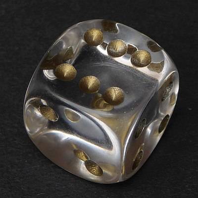
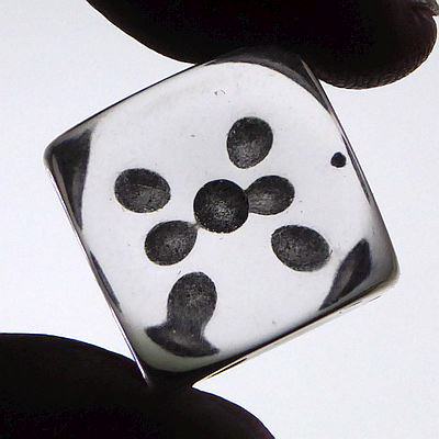
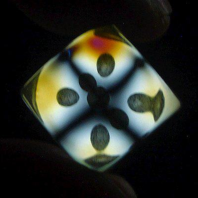
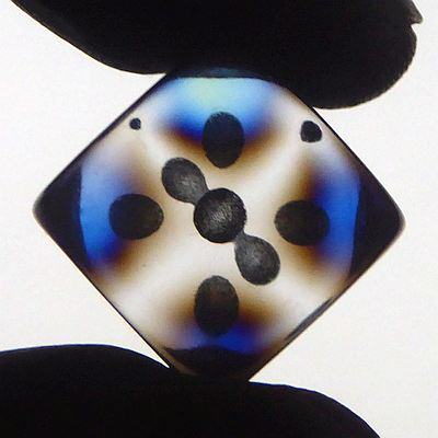
Today, to see this effect, no specially prepared glass specimens are necessary, instead, objects made of acrylic glass or other transparent synthetic resins made by injection moulding may be used. Beakers or round lids are very suitable as their inner tensions and orientation of the filiform molecules are nearly rotationally symmetric.
)
)
A plastic beaker in front of the white screen of my computer, photographed with a polarising filter. To the left the polarising filter blocks the light from the screen (“crossed polarisers”) and a dark cross is seen; to the right the polarising direction of the filter is the same as that of the screen and a white cross appears.
Due to the rotational symmetry of the pattern of birefringence, light that enters the material is split into one part polarised in the radial direction and another part polarised tangentially. After passing the polarising filter, what remains interferes and thus parts of the spectrum are suppressed, others enhanced. But if the impinging light oscillates in radial or tangential direction already before entering the material, there is no splitting, as the other component is zero, and there is no interference. This happens along two diameters orthogonal to each other which form a dark or a bright cross, depending on the orientation of the analysing filter. (The colours arising from interference have been dealt with in a special section.)
Of course, the pattern of internal tensions of Goethe's glass squares was not rotationally symmetric, but the symmetries of the square produce quite similar patterns.
Goethe describes his experiments correctly, but in his interpretations and attempted explanations he is ensnared by his ideas on the origin of colours.
Now consider the simplest experiment where no black mirror is used. The glass square lies horizontally on dark ground and mirrors the blue sky. The blue sky is sunlight scattered by air molecules (Rayleigh scattering), and is polarised with the electric vector at right angle to the sun's rays. We consider the case that the electric field oscillates in the plane spanned by the incoming ray and the perpendicular to the glass (p-polarisation), and the incoming ray's angle is close to the Brewster angle. In this case, there is little reflection at the surface, the light refracted into the glass is split into two rays (ordinary and extraordinary ray). The reflection at the bottom surface of the glass acts like a polarising filter because of the near Brewster angle, and so the situation is that of a birefringent medium between crossed polarisers. The first polariser is Rayleigh scattering, the second one the reflection near Brewster's angle. Colours and the black cross appear. If the incoming light is polarised horizontally (s-polarisation) the bright cross can be seen. The following two photos of a plastic lid reflecting the white computer screen have been taken without polarising filter; the colours are the same as seen with the bare eye.
)
)
With a bit of good will in the left picture the black cross can be seen, and in the right one the white cross. As the light from the screen is polarised obliquely, I had to position my “entoptic” plastic lid obliquely too to demonstrate this effect.
We see the dark cross if p-polarisation prevails, the bright cross in the opposite case.
Goethe was fascinated by the colours arising in crystals, mica sheets, or glass between polarising black mirrors, as expressed in a poem (no translation). Here is another plastic beaker:
)
)
)
The coloured reflections on compact discs are well known and an everyday experience. But similar colours could also be seen on the old vinyl discs, though only at grazing incidence of the light. To the right there is a photograph taken in about 1960.
)
When I was going to abuse an old vinyl (which I couldn't play any more) to serve as disc of a Wimshurst machine, I was surprised to see faint colours on it in the spotlight. Not at all grazing incidence, instead lit and viewed from almost perpendicular directions.
The colours bear some slight resemblance to Quetelet fringes as well as to those of thin films. The fringes seem to be circular. My first idea therefore was to look for light paths with slightly differing lengths, possibly with two reflections in the grooves, in analogy to the Quetelet mechanism. There are such paths as shown in the sketches at the end of this short section. The two rays coming from the same groove cannot be resolved by the eye, so the waves are superposed on the same spot of the retina (or the camera's sensor) and interfere to produce the colours well known from soap bubbles, oil films on wet pavements, generally from two-beam interference.
Using a small LED torch I tried to reproduce the effect with other old vinyls. It turned out that under similar conditions the results with different discs were quite different, presumably because of the shapes of the grooves' cross sections. Below are some examples.
The last picture in the row shows the record where I first saw the effect (which survived the unsuccessful test as a Wimshuest machine disc with minor injuries). Click on the images for larger versions! The sequence of colours is quite different from that seen in soap films or other examples of two-beam interference which means that the physics is not so simple: the grooves are so narrow that diffraction effects must not be ignored. Instead of accounting only for the paths where the light is deflected by specular reflection, we should, in the spirit of Huygens and Fresnel, consider the elementary waves scattered from all points along the cross section of the groove, scattered once more and finally forming the outgoing wave.
)
)
)
)
We have seen that small surface elements of black paper glisten in different colours, and as the surface structure there is irregular, the pattern of coloured specks is irregular too. Here now the surface is structured by slightly wiggly grooves with constant cross section. If at a certain point some colour is reflected at given illumination and observation angles, along the groove the colour changes only slowly, and the neighbouring grooves, having the same cross section and viewed and illuminated at almost the same angles, are likely to show nearly the same colour too. Therefore there are “regular” fringes instead of chaotic speckles.
)
)
)
A sheet of black cardboard in the sunlight. It looks inconspicuously, black or, more precisely, dark grey. But when looking at it closely in the direction to the sun, a pattern of colourful tiny specks can be seen. The image to the right is an enlarged detail of the left one. At the bottom the millimetre-scale of a set square.
)
)
I remember that once I have read about this phenomenen in Goethe's “Colour Theory”. This book, scanned and digitized, is now accessible in the web in the “Deutsches Text-Archiv”, here is the citation:
)
|
|
Of course, a correct explanation is not to be expected from Goethe. Diffraction and interference produce this effect, as has been discussed in detail in the corresponding section.
The dark brown fur of the dog in the next image is shimmering. The effect is much the same. Colours are seen where the gloss of the fur is slightly out of focus, and pink and green prevail.
)
)
A similar observation has also been described accurately by Goethe:
) |
|
(The text images have been derived from the scans of the Deutsches Textarchiv. Goethe, Johann Wolfgang von: Zur Farbenlehre. Bd. 1. Tübingen, 1810.)
Back to the page "the origins of colour" or home.
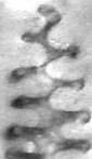
)
)
)